Dimensional Tolerances
Control of Distortion
Depending on the design of the part and its mold, some distortion may occur during cooling and solidification. The following tables show tolerances which may be expected with respect to given planes and shapes.
Flatness Area*/TIR
4 in.2 – .010
16 in.2 – .015
36 in.2 – .025
Straightness Length*/TIR
Up to 6″ – .010
6″ to 15″ – .020
15″ to 30″ – .040
Over 30″ – Negotiated
Maximum Size: 36″ x 36″ x 36″
Maximum Weight: 50 lbs.
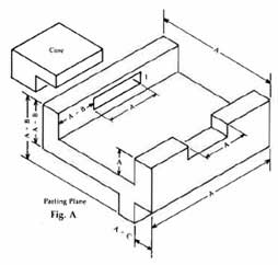
Tolerances (in inches, refer to Fig. A)
Parting Plane – Fig. A
“A” Dimensions: Any dimension contained completely within one mold half or within a core.
“B” Dimensions: To compensate for a compression of plaster mold halves at the parting line, or for hand positioning of cores.
“C” Dimensions: To compensate for possible mismatch or shift when mold halves are assembled.
NOTE: Where “B” and “C” tolerances affect critical dimensions adversely, they often can be eliminated by relocation of the parting plane.
Angles Normal: ±1/2°
Radii Normal: .030″
Surface Finish: 125 RMS or better
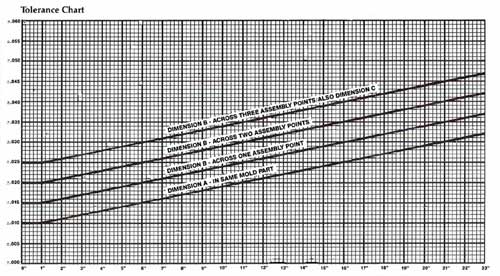
Length/Size – Normal Tolerance
0″ to 1″ – ± .010
1″ to 6″ – ±.015
6″ to 11″ – ±.020
Over 11″ – Add ± .001/inch
Add ±.005 across one assembly point
Add ±.010 across two assembly points
Add ±.015 across three assembly points
Add ± 0.15 to “A” length tolerances
NOTE: Specifications, mechanical properties and tolerances given are nominal, and to be used as design considerations with Supreme’s engineers as early in the design process as practical. The size and shape of an individual casting can effect tolerances, thus figures presented are not absolute.
*Design Data
Flatness and straightness limits are largely governed by the ability to mechanically straighten a casting. The values listed are based on a typical rectangular piece on which flatness was checked with a straight edge and feeler gage.
Section Thickness
Depending on design and size of the part and its associated mold, minimum wall thickness achievable through use of the plaster mold process ranges from .050″ for smaller parts to .090″ for larger ones.


